01
Context
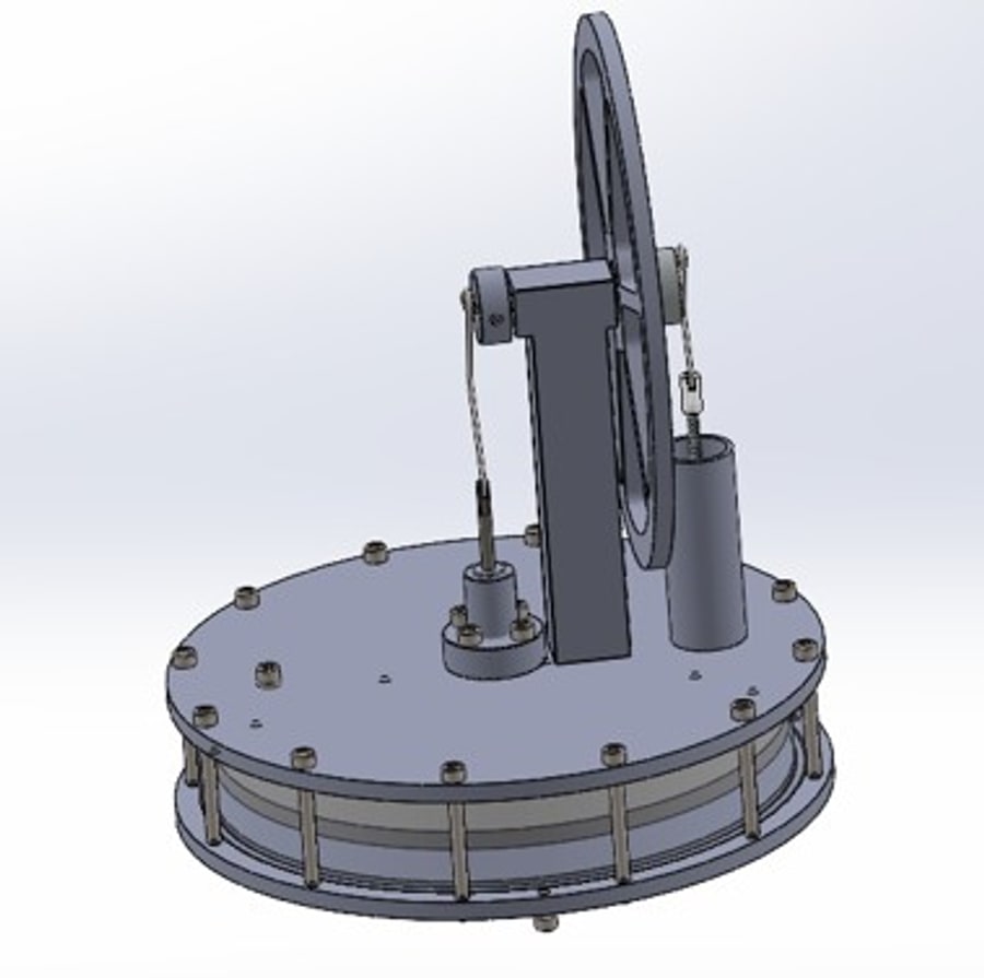
Stirling engines turn a temperature difference into mechanical energy. I fabricated a Stirling engine that operates on the temperature difference between room air and a tray of ice. I then re-designed the baseline engine to run faster with better build quality, targeting its two biggest losses: heat and fluid flow, and friction and misalignment.
02
Redesign & analysis
Every change came from a first-order calculation:
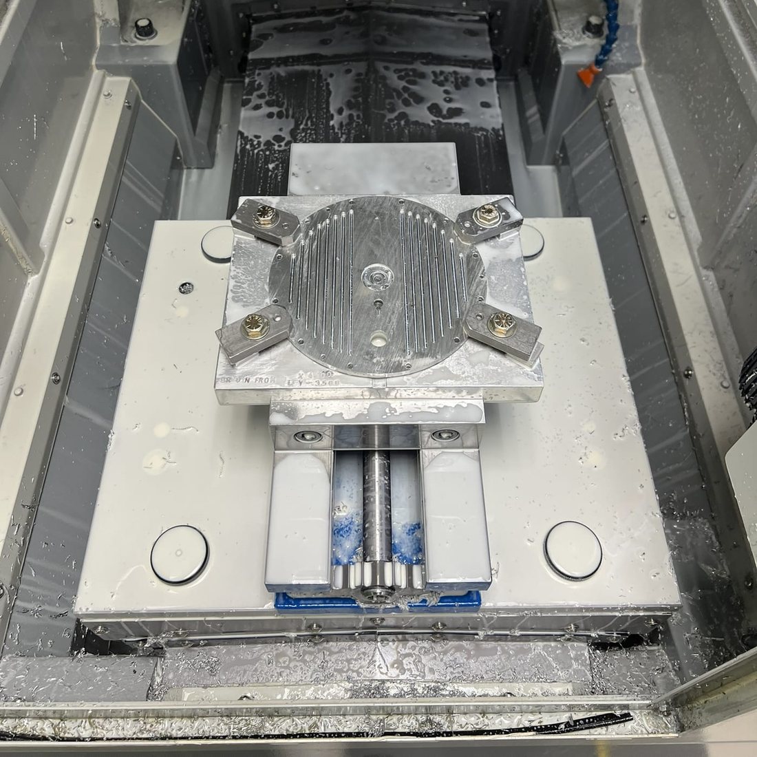
- Cooling fins. By Newton's law of cooling, heat rejection scales with area — so I CNC-milled 16 slots into the top plate (~7.5% more surface area) to hold the temperature difference that drives the engine.
- Low-conduction fasteners. The bolts clamping the hot and cold plates were shorting heat between them; swapping nine from steel to nylon (k: 14.4 → 0.25 W/m·K) cut that path by >98%.
- Rounded displacer. Treating the displacer gap as an orifice, rounding its edges and widening the gap lowered the loss coefficients and flow velocity, reducing pumping losses.
- Low-friction linkages. I replaced the steel-wire links (μ ≈ 0.42, steel-on-steel) with 3D-printed links on shoulder bolts and press-fit bearings (μ ≈ 0.002) — a ~99.5% cut in linkage friction.
03
Fabrication & testing
Everything was made with common shop processes — mill (manual and CNC 2op), lathe, laser cutting, and 3D printing.
04
Results
Engine speed rose from 50 to 120 rpm upon redesign.