Background & motivation
Methane pyrolysis offers a route to producing hydrogen and solid carbon without directly generating CO₂. My MPhil research investigated the use of iron nanoparticles as catalysts for carbon-nanotube growth, which required a method of generating and delivering controlled quantities of catalyst particles into a high-temperature reactor. I designed the particle-generation subsystem, developed the supporting numerical models, and designed the experimental campaign used to characterize the resulting particles.
Experimental setup
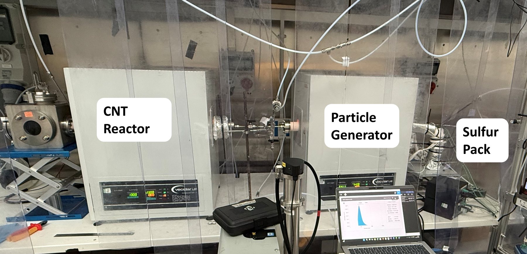
A carrier gas — argon or hydrogen, optionally carrying sulfur vapour — flows over a boat of iron powder inside a tube furnace. The iron evaporates, cools as it travels downstream, and nucleates into a nanoparticle aerosol that is drawn off through an extraction tube. The metered gas supply feeds the generator, and a second furnace grows carbon nanotubes from the delivered particles.
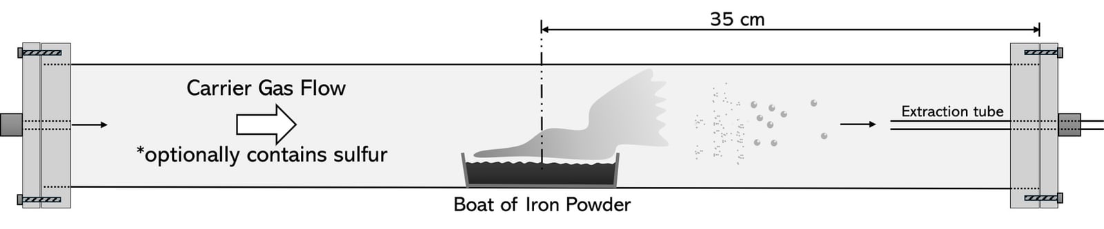
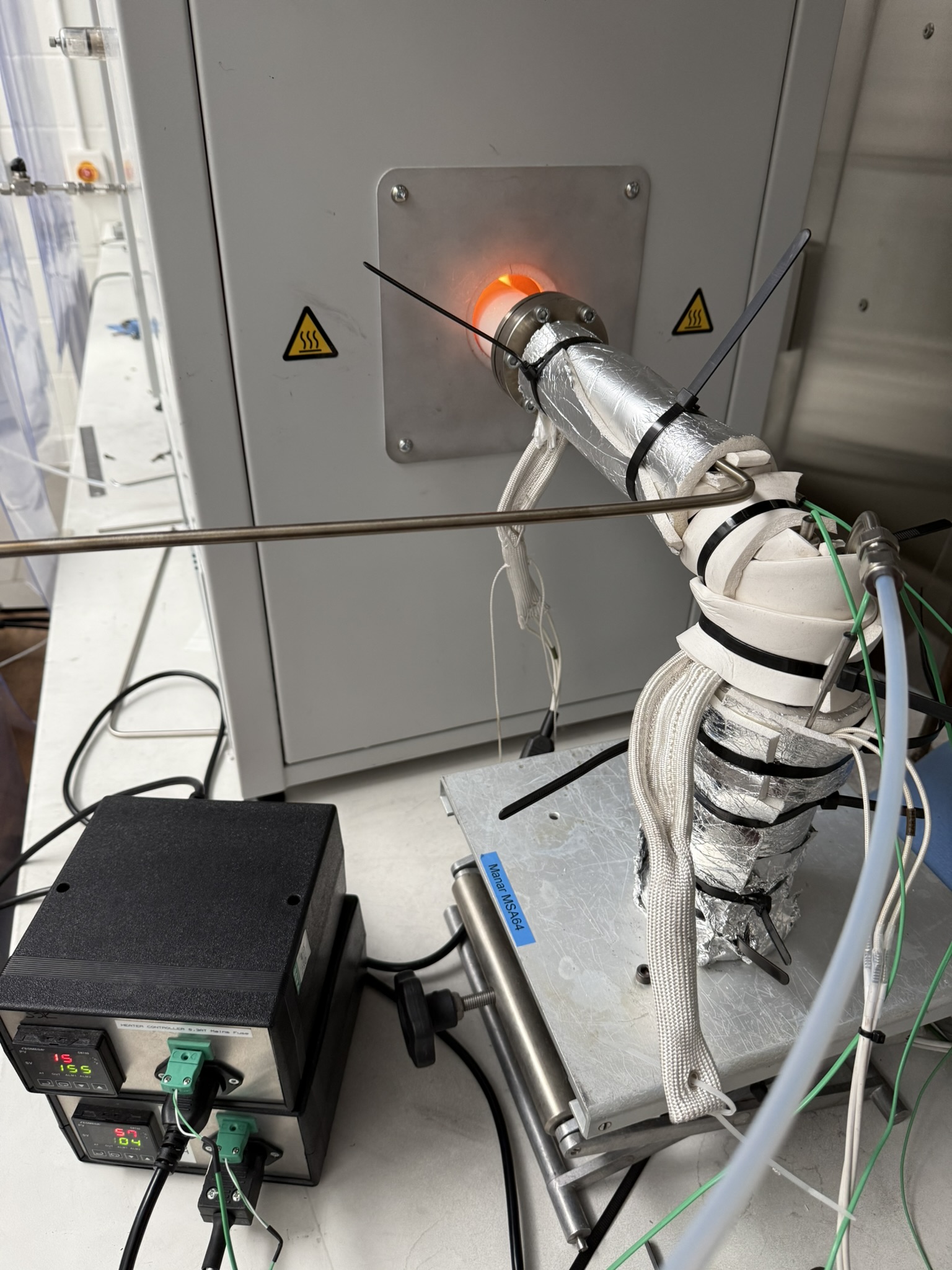
I designed the particle generator and built the sulfur sublimation subsystem — a heated pack and an insulated delivery line held above the sulfur condensation point along its full length — and integrated it with the reactor's mass-flow-controlled gas panel and counterflow CNT reactor.
Design & analysis
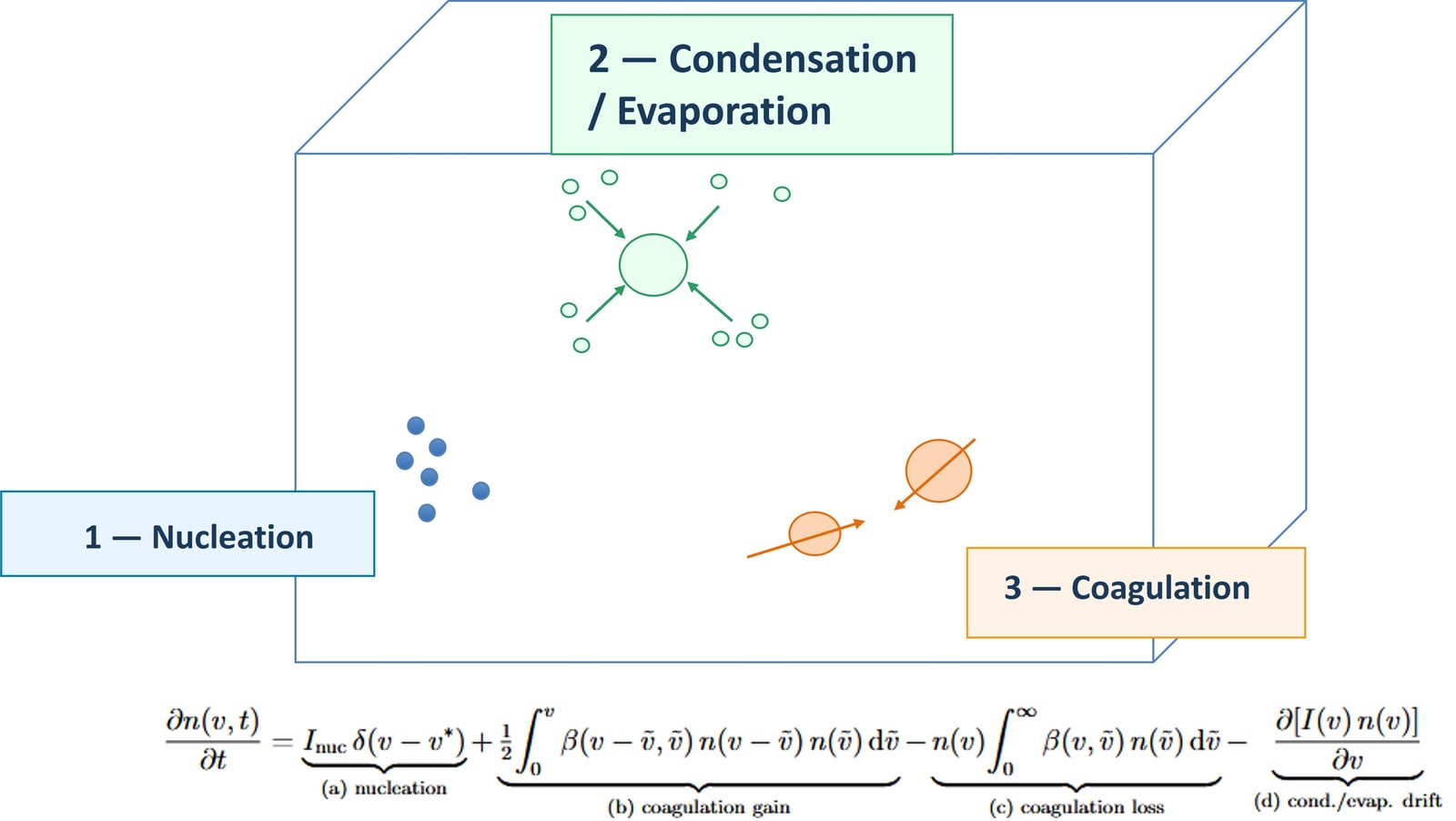
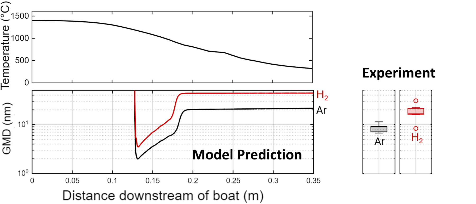
Before building, I modelled the iron aerosol as it travels the reactor, tracking three competing processes — nucleation, condensation/evaporation, and coagulation — along the measured temperature profile. The model let me reason about where particles form and how their size and number evolve, and to pick operating points before committing hardware.
A few analyses drove concrete design decisions:
- Reactor thermal profile → extraction geometry. The axial temperature field sets where the vapour cools and nucleates, so I positioned the extraction tube where the aerosol is fully formed and chose the furnace setpoint accordingly.
- Coagulation timescales → transport strategy. The model showed how quickly particle number is lost downstream, which motivated extracting and transporting the aerosol at low temperature to preserve it.
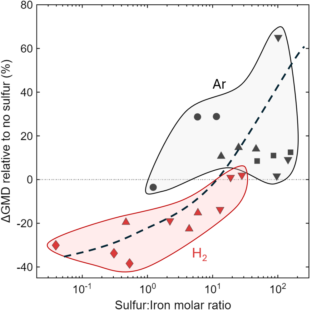
- Vapour-pressure (Antoine) calculations → sulfur delivery. These sized the sulfur-pack temperature range used to target a given sulfur-to-iron ratio, which set the heater's operating window.
Characterization
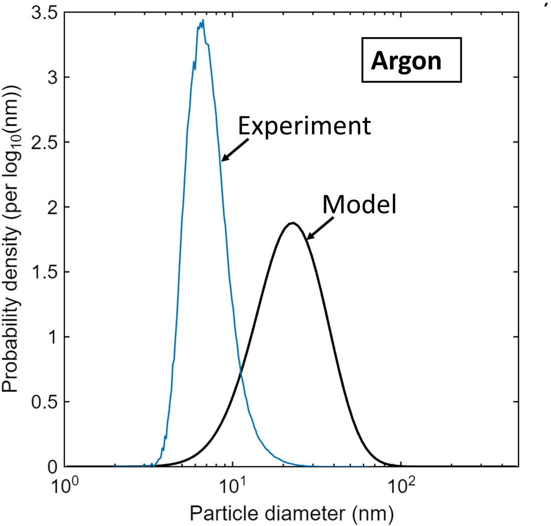
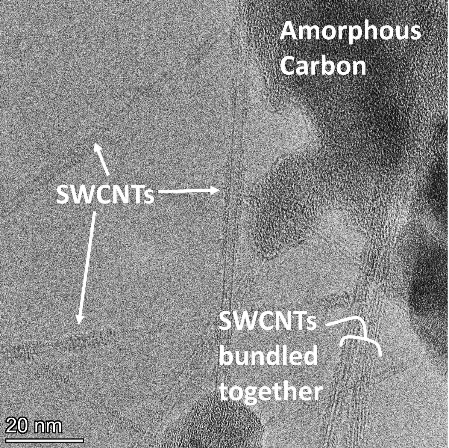
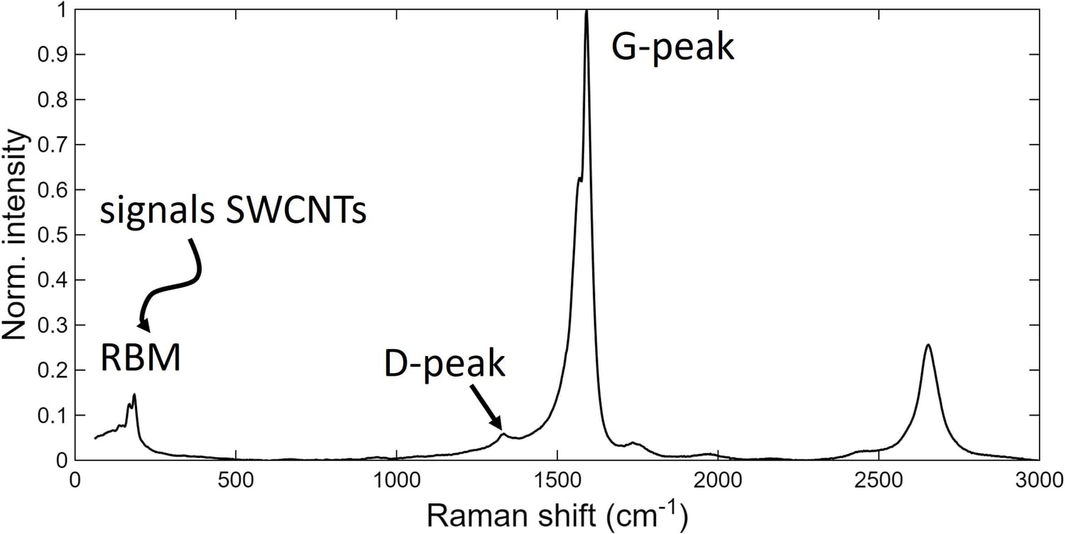
To confirm the system produced what it was designed to, I characterised both the catalyst particles and the carbon product. Transmission electron microscopy (TEM) imaged morphology — resolving individual single-walled nanotubes and distinguishing them from amorphous carbon. Raman spectroscopy probed the graphitic structure of the carbon, using the radial-breathing, D and G bands to identify single-walled tubes and gauge quality. Catalyst particle size distributions were measured live with a scanning mobility particle sizer (SMPS) — the primary quantitative readout behind the results below.
Results
- Model-guided diagnosis. Comparing the model against measurements let me trace an unexpected rise in particle number concentration to the carrier gas — hydrogen was chemically reducing impurities in the reactor tube into background particles that seeded nucleation. The discrepancy became a diagnosis rather than an error.
- Controlling coagulation with sulfur. Dosing a small amount of sulfur measurably suppressed particle coagulation and reduced the mean particle size — a controllable knob for tuning the catalyst population.
- High-value product. The generator grew carbon nanotubes with quality/crystallinity that is consistent with high tensile strength and electrical conductivity.